CBV-fMRI with VASO is highly dependent on a good inversion contrast. It gives it its CBV sensitivity and is also responsible for most of the VASO specific pitfalls (e.g. inflow, CSF etc. ). And thus, it should be optimized as much as possible.
In this blog post, I want to describe the most important features of a reliable inversion pulse for the application of VASO at 7T with a head transmit coil.
Pulse features
One of the most SAR-efficient adiabatic inversion pulse for 7T the TR-FOCI pulse class developed in Nottingham. While the original TR-FOCI pulse is optimized to achieve a sharp slab profile, VASO is not so much limited by sharpness. Instead, inversion in VASO it rather limited by SAR-efficiency and inversion range. Thus, it can be beneficial to reduce the bandwidth of the TR-FOCI pulse for VASO applications.

Required B1+field
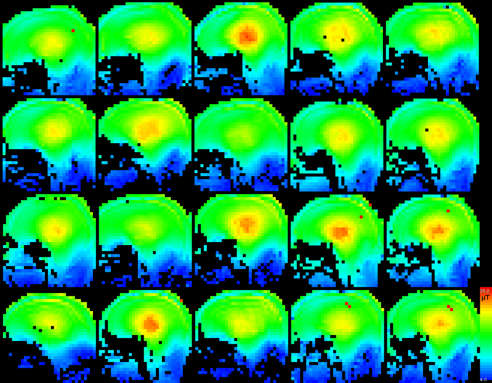
In the original TR-FOCI paper, Hurley et al. state that a peak amplitude of 7μT are sufficient to achieve a complete inversion. In my own validation experiments (figure below), I found that this is only true in phantoms with unrealistically small off-resonances. In-vivo, however, I find that in actual experiments at least 7.7 μT are necessary. When additional off resonances are present, like in feeding arteries at the base of the brain, I would recommend to add an extra safety margin. This is particularly necessary because we use lower bandwidths (4.7 kHz) than the original TR-FOCI pulse (6.4 kHz)

B1-independent way of reducing the inversion efficiency to minimize inflow effects
In SS-SI VASO, inflow effects can be challenging. As such, in brain areas with very short arterial arrival times (e.g. Auditory and or insular cortex) or in combination with global respiration tasks that reduce the arterial time (e.g. breath holding and hypercapnia). In those cases, it can happen that in the time period between the inversion and the excitation, fresh (non-inverted) blood reaches the micro-vessels of the imaging slab. This fresh blood results in a FAIR-like CBF contamination that counteracts the VASO contrast and should be avoided.

Technical implementation of the B1-independent reduction in inversion efficiency
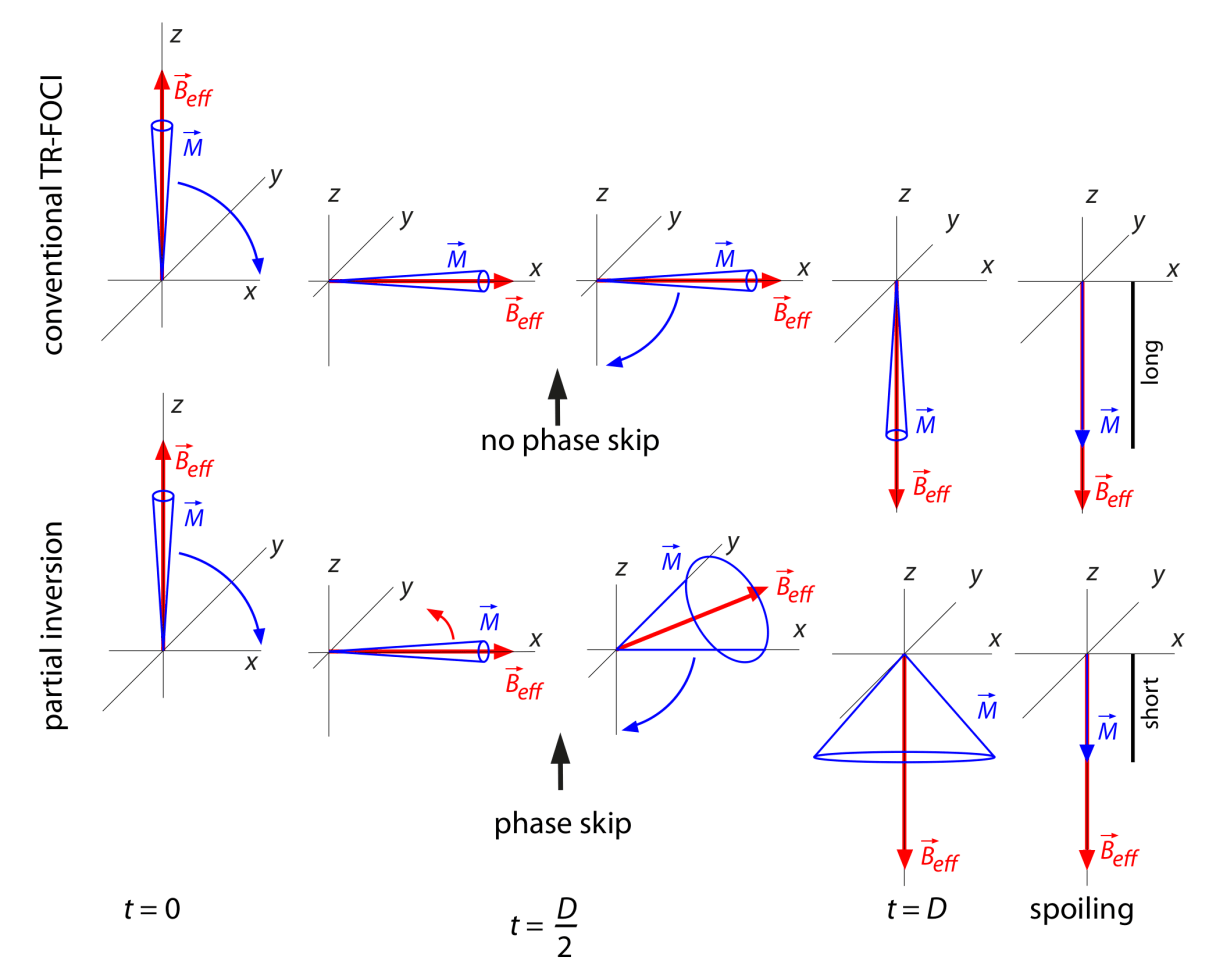
In order to achieve an adjustable inversion efficiency in a B1-independent manner, the concept of RF phase modulation during the RF pulse can be applied. Such phase modulations are known from plane rotation pulses for flip-angle variations [Norris and Haase, 1989] and were transferred to conventional (non-planar) adiabatic pulses. The reduction in inversion efficiency can be achieved by introducing a phase skip of the RF field, B1, during the inversion exactly at the time when the frequency of the adiabatic pulse is on resonance. The corresponding shape functions of the amplitude and phase of the RF pulse is shown in the figure below.

A more intuitive illustration of the working principle of the new partial inversion pulse is illustrated blow. In conventional adiabatic inversion pulses, the magnetization precesses around the effective magnetic field at the surface of a narrow ‘cone of precession’. During the frequency sweep of adiabatic RF pulses this cone usually follows the effective magnetic field, while it changes its direction. When a phase skip of the RF pulse is applied, this ‘cone of precession’ opens up. After inversion, the ‘cone of precession’ points along anti-parallel to the z-direction. The B1-independent reduction in inversion efficiency is then given by the transverse component of the magnetization, which depends directly on the phase skip applied. The reduction of the inversion efficiency is given by the cosine of the opening angle.
It is important to note, however, that the reduction of the TI to minimize inflow effect, also comes along with a reduced GM signal and reduced VASO sensitivity (See PhD Thesis Fig. 4.24).
Stability across participants
Personally, I found the TR-FOCI pulse very reliable across people. In fact, I find the inter-subject variability smaller than the error of the transmit adjust calibration scan. And thus, with the 32ch Nova coil, I fix the transmit voltage to 220V independent of the persons head size. The B1+ field maps blow confirm that the threshold of 7.7μT is exceeded for all people well below the circle of Willis.

Other comments
- It is to note, that the first VASO versions actually had a gradient implemented to make the SS-SI-VASO real slab-selective. In practice, however, it turned out that the slab thickness should be thicker than 14cm. Thus, the slab-thickness it actually larger than the range of the transmit coil coverage. As a result, the gradient is switched off for all scans with head-transmit coil only.
- The inversion pulse can be implemented in multiple ways in the sequence.
- In most of the SIEMENS VASO sequences, it is implemented as an ARB_rf. This means the pulse shape is calculated in real time based on the equations given from Hurley.
- In the SIEMENS pulse-tool with this pulse tool file.
- In Bruker with this pulse file.
- This pulse file has also been applied on Phillips scanner by Peiying Liu.
- The B1/B0 and SAR constraints are amplified at even higher field strengths of 9.4T. There, additional precautions need to be considered. This is described here: https://www.ncbi.nlm.nih.gov/pubmed/29890330
Further Reading
- Theoretical background of TR-FOCI pulses in Chapter 2.3.3 page 22 of the Masters thesis here.
- Regime of reliable parameters of the TR-FOCI pulse in Chapter 6.1-6.3 (page 60) of the Masters thesis here.
- Strategies to avoid inflow with reduced inversion efficiencies in Chapter 4.3 (page 123) of the PhD thesis here.
